top of page
 |  |  |  |
|---|
Stress and Structural Design
AIRBUS Engineering Center Co., Ltd (AIRBUS GROUP)
Beijing, China & Illescas, Spain
Stress Engineer
Nov 2018 – Apr 2021
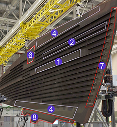
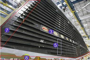
Components I have worked on.
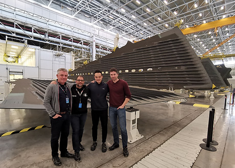
A350 Wing Lower Cover Stress and Design Team
(Mike, Pako, Victor, and Rafa), Illescas, Spain
-
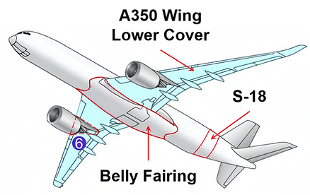
Stress Analysis and Justification for A350XWB-900/-1000 Wing Lower Cover:
-
Led damage tolerance and stability analysis on carbon fiber reinforced plastic (CFRP) skin panels ①, stringers ②, manhole rebates ③, and spar interfaces ④, ensuring compliance with AIRBUS design standards.
-
Performed bolted joint analysis on rib-to-skin ⑤ and pylon-to-skin ⑥ interfaces using FEM and ISAMI-Column Beam Analysis, -Damage Tolerance, -Panel Buckling, and -Filled Hole Modules, ensuring interface integrity under service loads.
-
Executed COMBA (1D, 2D) and non-sleeve crack analysis to assess and justify bonding repair solutions.
2. GFEM Validation for A350 Section 18 & Belly Fairing:
-
Implemented FEM modifications for each MSN aircraft by adjusting geometries, material properties, and laminate stacking sequences.
-
Re-meshed the model, applied boundary conditions and loads, and performed model integrity checks (warping, skew angles, coincident nodes/elements).
-
Conducted static, dynamic, and thermal validations to ensure model accuracy and regulatory compliance.
3. DFEM Analysis for CFRP Wing Manufacturing Defects:
-
Performed DFEM assessments for critical manufacturing deviations (e.g., multi-delamination, material shortages, excessive porosity) in high-stress zones (e.g., stringer run-outs, spar edges).
-
Evaluated repair solutions by analyzing micro-strain, flux, and displacement distributions.
-
Calculated reserve factors to confirm design safety and validate repair strategies.
Project on Metal Forming Simulation
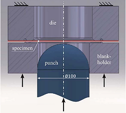
Hemispherical dome test setup.
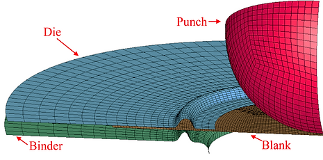
Meshed geometry of different components.
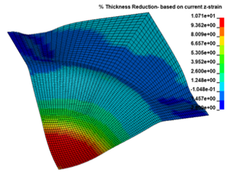
Percent thickness reduction.
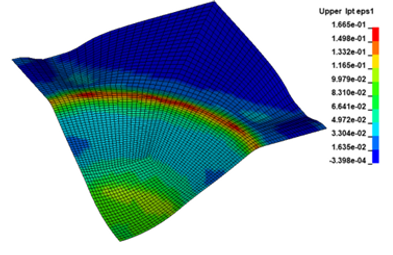
Major true strain contour.
Objective:
Develop and validate numerical models of a 100 mm hemispherical dome test to investigate strain distribution and formability behavior of sheet metals under biaxial loading conditions.
Model description:
-
Blank material: 5754 aluminum alloy (anisotropic).
-
Mesh on blank: Quadrilateral 4-node shell + 7 integration points + 2 mm thickness.
-
Mesh on other components: Quadrilateral 4-node shell + 3 integration points + 1 mm thickness.
-
Mesh size: 1 mm (high strain gradient regions) + 5 mm (other regions).
-
Boundary conditions: Quarter symmetry.
-
Test conditions: 30 mm punch displacement + 20 mm/ms peak speed.
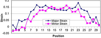
Strain plots versus position.
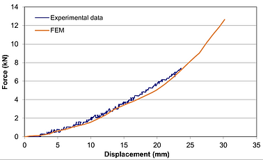
Experimental and simulated punch load versus displacement curves.
Project on High Speed Impact Simulation
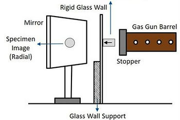
High speed impact test setup.
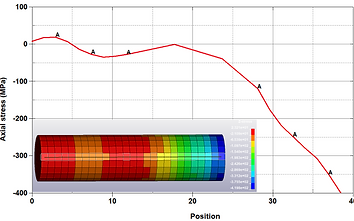
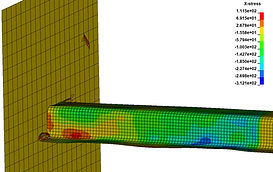
Axial stress versus position along the specimen when the unloading wave is at the midpoint of the length of the specimen.
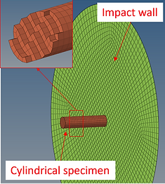
Meshed geometry of different components.
Model description:
-
Material: AA7075-T6 (specimen) + steel (wall), non-linear.
-
Mesh on specimen: Hexahedral 8-node solid + full integration + 10 mm diameter + 40 mm length.
-
Mesh on wall: Quadrilateral 4-node shell + 8 integration points + 200 mm diameter + 8 mm thickness.
-
Mesh size: 1.5 mm (specimen) + 5 mm (wall).
-
Boundary conditions: x and y translational + x, y, and z rotational constraints.
-
Test conditions: 27.2 + 25x mm/ms impact velocity.
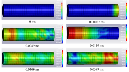
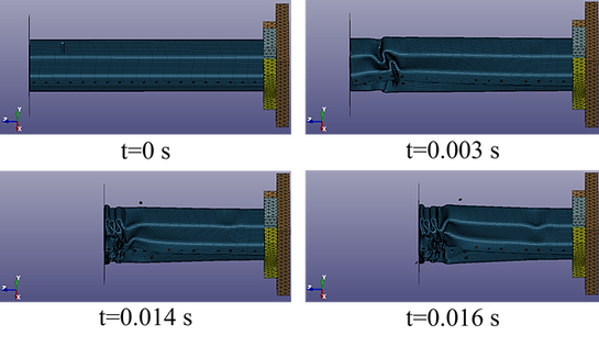
Velocity profiles of the specimen at different time.
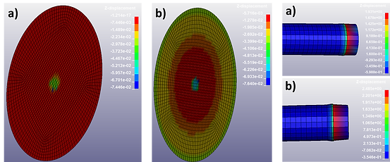
Deformed shape of the specimen and target wall at 0.0060 ms (a) and 0.04997 ms (b).
Objective:
Develop and validate numerical models of a solid cylindrical rod impacting plates made of various materials to assess the effects of impact velocity and target material on plastic deformation behavior.
Project on Axial Crush Simulation
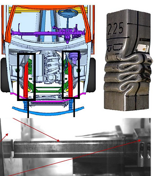
Front crush channels made of FRP composites and metals.
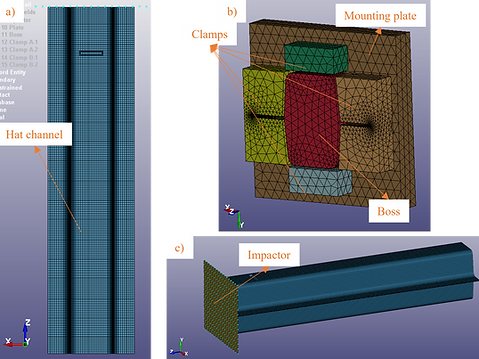
Meshed geometry of different components.
Objective:
Model the dynamic axial crush of hat channels made of steels and composites to evaluate the crush response, including deformation modes, cracking, folding (metals), fragmentation (composites), force vs displacement response, and the absorbed energy.
Model description:
-
Channel material: UD-NCF carbon fiber/epoxy (linear-elastic) + steel (non-linear).
-
Mesh on channel: Quadrilateral 4-node shell + 1 integration point for each ply [0/±45/90]s + 495 x 44 x 50 mm + 2.7 mm thickness.
-
Mesh on Impactor: Quadrilateral 4-node shell (rigid).
-
Mesh size: 5 mm (channel) + 10 mm (impactor).
-
Boundary conditions: Channel fully constrained along a 50 mm length.
-
Test conditions: 855 kg impactor mass + 10.6 m/s impact velocity.

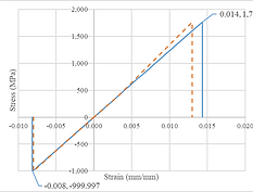
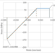
Single-element simulation to validate material model MAT54.
Metal deformation over time.
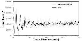
Experimental and simulated crush force versus distance curves (UD-NCF carbon fiber/epoxy).
bottom of page